|
Takeaway points
Should I use a 4-legged mount?
All things being equal, use any of our 3-legged mount. 3-legged mounts are symmetrical, and provide a very elegant decoupling between in-plane and out-of-plane loads and deformations. However, if your geometry prefers 4 mount points, don't hesitate to use one of our 4-legged mount. They are every bit "as kinematic", equally ruggedized, and can actually reduce bending stresses caused by unnessesarily large overhangs. |
Four Legged Kinematic Mounts
Three Legs Good, Four Legs Bad?
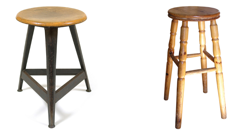
When it comes to bar stools, there is very little doubt. A three-legged stool is kinematic and thus stable. A four-legged stool – not so much. But does it follow that a four-legged kinematic mount is impossible? Consider: The bar stool is assumed to be free in X-Y-Theta — it can be moved and rotated freely in the plane of the bar. So only three degrees of freedom (DOFs) are really constrained, and therefore four legs are just one leg too many. But unlike the stool, a kinematic mount has to constrain all six degrees of freedom, which means that the "stool argument" does not really apply. From a kinematic point of view, a stable four-legged mount can be made as long as the number of constrains adds up to six. * In fact, it is possible to create a four-legged stool, but it requires creating an additional internal DOF so that the stool is no longer a rigid body. This is done with our FLF product line. Traditional kinematic mounts (such as cone-groove-flat, 3-groove, or our Spherolinder or three-bead mounts) always use three mating sites to support their loads. This is less than ideal sometimes, since many objects in the real world (e.g. optical breadboard, pallets, AGVs...) are in fact rectangular, and are better supported at four corners rather than at three. There's more than just esthetics at stake. Complex composite objects such as car bodies on an assembly line only have structurally-sound mating points at their corners, near the suspension anchors. A similar situation exists between granite optical beds and their rectangular support weldments, which are most stiff near their legs, and much less so in mid-span. Luckily, however, (see sidebar, right) there is no fundamental inhibition to making a four-legged kinematic mount. The simplest implementation of such a mount uses a "Pivot" mating element at one of the corners and "Link" mating elements at the other three. The Pivot element constrains three translational degrees of freedom, leaving three rotational ones free: in-plane, tip, and tilt. The three Link mating elements each constrain one degree of freedom - the distance between two fixed points on the two components. In order to provide a kinematic solution, the first mathematical condition levied on the three Links is that the direction vectors of the torques they apply in relation to the Pivot be linearly independent. Any combination of three Links that fits this bill will create a kinematic mount. On top of being linearly independent, in order to provide adequate load support, all three Links need to have a substantial component in the direction perpendicular to the optical table. To reduce the need for clamping, the Links need to be placed so that when they act in compression, the torques they generate around the vertical axis will be counteracting. 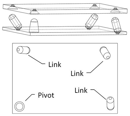
We can satisfy both these conditions using the conceptual geometry shown on the left, using (in this case) "pill type" link elements This implementation is good for illustrative purposes, and in fact can be implemented and investigated using 7 tooling balls and 1 counter-sunk rod, as shown below. (Download drawings) This mount, however, is not practical for real-life use, since it is highly non-symmetrical, and uses point contacts. 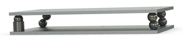
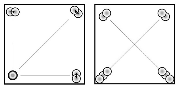
A variety of geometries can be constructed using two 1-DOF elements and two 2-DOF elements. A schematic diagram of one such configuration that is used by our producs is shown on the left, next to the diagram for the previously described mount. This "2-2-1-1" configuration is more symmetrical, has a larger stable zone, and has less cross-talk between in-plane and out-of-plane forces and deformations. Additionally, the product mounting elements are ruggedized by eliminating point contacts in favor of line contacts, much as was done when ruggedizing three-legged kinematic mounts. Note that in the 2-2-1-1 configuration, the alighment of the 1-DOF element is always such that they oppose each other, and are perpendicular to the intersection point of the bisectors of the 2-DOF elements, which is this specific case is located at the center of the square plate. The above principles are demonstrated in the video below. (Text continues afterwards) Catches and Caveats
There is no such thing as a free lunch. While four-legged kinematic mounts are very convenient and powerful, they do have one significant drawback when compared with three-legged kinematic mounts: they give up the elegant de-coupling that existed between in-plane and out-of-plane forces and deformations. For example, if one of the mating elements was positioned with a certain in-plane deviation from its nominal location, the resulting assembly might have an out-of-plane deviation between the components. Horizontal non-retained three-legged mounts clearly tip over when the c.g. travels outside of the triangle defined by the legs, and are relatively less sensitive to horizontal forces. Horizontal non-retained four-legged mounts are less intuitive in that placing the c.g. in close proximity to the 1-DOF legs, even if inside the rectangle defined by the legs, can still cause them to tip over. (This is mitigated of course, in both cases, by using retainers.) Our recommendation therefore is to use three-legged kinematic mounts as a first alternative, but not to hesitate to use four-legged mounts when they fit the geometry, since they are every bit as kinematic, and perform just as well. Educational Demo Kit
| ||||
| 650-605-4500 | ©2017 g2-engineering |